


- Home
- Products
- CNC Machines
- QUASER MACHINE TOOLS, INC.
- MF700 Multi-face/5-axis Machining Center

QUASER MACHINE TOOLS, INC.
MF700 Multi-face/5-axis Machining Center
Share:



Machine Introduction
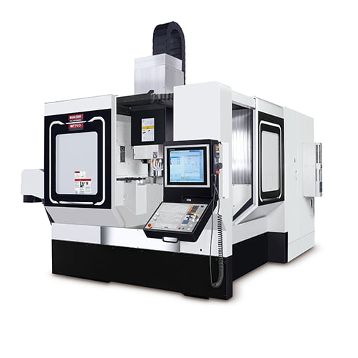
The MF700 adopts a moving column C-type structure with a design of three-axis overlap and two-axis separation. Compared with the "actual" strength of the same configuration on the market, it is further optimized using FEM to produce a product that meets the rigidity of the Bausch & Lomb standard. It isolates the three axes from the cutting zone to avoid cutting contamination and facilitate maintenance.
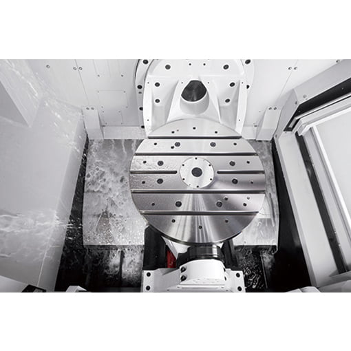
The linear axis features a cross-shaped design, supported by a wide-span column and large-size sliders, ensuring excellent stability during high-speed cutting. The Y and Z axes employ a three-slider configuration to enhance the stability of the moving structure. The wall-mounted rotary table integrates the tilting axis within the machine tool, resulting in a smaller footprint, a more compact design, and a larger machining area, providing optimal space utilization and accessibility to the machining area.
The double-sided support tilting axis enhances load-bearing capacity, allowing the rotary table to carry workpieces weighing up to 500 kg, with a maximum workpiece diameter of 700 mm and a height of 500 mm, facilitating the machining of various types of parts. The standard configuration of the rotary table employs a worm gear and ring-type brake design, featuring high rigidity, high torque, and high locking force. Future upgrades to dual-motor rotary tables will provide even higher speeds and precision, further meeting the machining needs of the aerospace industry.
The two-way door opening design facilitates operator observation and operation, and an automatic door is optional to meet production automation needs. Three top covers are available: a telescopic top cover, an integrated top cover, and an open top cover. The MF700 has a standard tool capacity of 48 tools, with upgrade options of 60, 90, and 120 tools to meet more diverse usage requirements.
The chip removal system is a direct chip discharge type, where chips are quickly and in large quantities discharged directly through a high-efficiency chip conveyor under the machine, saving machine tool maintenance time.
The linear axis features a cross-shaped design, supported by a wide-span column and large-size sliders, ensuring excellent stability during high-speed cutting. The Y and Z axes employ a three-slider configuration to enhance the stability of the moving structure. The wall-mounted rotary table integrates the tilting axis within the machine tool, resulting in a smaller footprint, a more compact design, and a larger machining area, providing optimal space utilization and accessibility to the machining area.
The double-sided support tilting axis enhances load-bearing capacity, allowing the rotary table to carry workpieces weighing up to 500 kg, with a maximum workpiece diameter of 700 mm and a height of 500 mm, facilitating the machining of various types of parts. The standard configuration of the rotary table employs a worm gear and ring-type brake design, featuring high rigidity, high torque, and high locking force. Future upgrades to dual-motor rotary tables will provide even higher speeds and precision, further meeting the machining needs of the aerospace industry.
The two-way door opening design facilitates operator observation and operation, and an automatic door is optional to meet production automation needs. Three top covers are available: a telescopic top cover, an integrated top cover, and an open top cover. The MF700 has a standard tool capacity of 48 tools, with upgrade options of 60, 90, and 120 tools to meet more diverse usage requirements.
The chip removal system is a direct chip discharge type, where chips are quickly and in large quantities discharged directly through a high-efficiency chip conveyor under the machine, saving machine tool maintenance time.
Product Specifications
Baide Group provides process technology and application expertise to achieve optimal product manufacturing performance.
| Technical data | MF700 |
|---|---|
| Scope of work | |
| Workbench size | Ø650 mm |
| Maximum workpiece diameter | Ø700 mm |
| Maximum workpiece size | Ø700 x H500 mm |
| X-axis travel | 820 mm |
| Y-axis travel | 570 mm |
| Z-axis travel | 530 mm |
| Workbench load | 500 kg |
| spindle | |
| Spindle type | 40 taper |
| maximum spindle speed | 12K ~ 20K |
| Automatic tool changer | |
| Tool magazine capacity | 48 (std.) |
| Maximum tool diameter | 76.2 mm |
| Maximum tool diameter without adjacent tools | 125 mm |
| Maximum tool length | 300mm |
| Machine size | |
| high | 3,670 mm |
| Floor area (width x depth) | 3,520 x 4,400 mm |
| weight | 10,500 kg |
Contact Us
If you have any suggestions or advice, please leave your valuable information and we will reply to you as soon as possible.